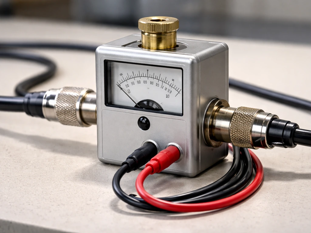
A Bird wattmeter is an inline RF power meter, most famously the Bird Model 43 or 4304A, that sits in a coaxial transmission line and measures how much radio-frequency power is flowing forward toward a load and how much is bouncing back. You connect it between your RF source and your antenna or device, insert the right plug-in sensing element (called a slug), point the slug in the correct direction, and read the power directly off the analog or digital display. That's the core of it. The rest of this guide walks you through every step so you can do it confidently and safely.
How to Use a Bird Wattmeter: Setup, Wiring, Readings

Marcus Hendricks
17 May 2026
What a Bird wattmeter actually is and what it measures
The Bird wattmeter is not a general-purpose plug-in energy monitor. It is a directional RF power meter designed specifically for 50-ohm coaxial transmission lines. The key word is directional. It can measure two things at once: forward power (energy traveling from your source toward the load) and reflected power (energy bouncing back from a mismatched load). From those two numbers you can also derive VSWR (Voltage Standing Wave Ratio) and return loss, which tell you how well your antenna or device is matched to the line.
The units are watts, and depending on the slug you insert, the measurement range can span from milliwatts all the way up to kilowatts. Bird makes slugs for specific frequency ranges and power ranges, so a single meter body can serve many different setups just by swapping the plug-in element. This modularity is one of the reasons the Bird 43 has been the go-to RF wattmeter for decades.
More modern Bird instruments like the 4421A add a digital display and can show Average Power, Pulse Power, VSWR, Return Loss, and Forward/Reflected power simultaneously on screen. But the fundamental measurement concept is the same across the whole Bird family.
How the Bird wattmeter computes power (the signal path explained simply)
Inside every Bird slug is a lumped-constant directional coupler. That's a fancy phrase for a tiny circuit that samples the RF signal passing through the line in two ways at once: blank" rel="noopener noreferrer">it picks up the voltage at the point of insertion using a capacitive probe, and it picks up the current using a small inductive loop. Those two samples are combined in a way that is sensitive only to power flowing in one direction, which is how the meter separates forward power from reflected power depending on which way you orient the slug.
At a deeper level, real power is calculated by multiplying instantaneous voltage by instantaneous current and averaging that product over at least one complete RF cycle. The result is active (real) power in watts. If the load is perfectly matched (no reflections), nearly all forward power reaches the load and reflected power reads close to zero. If there's a mismatch, some energy bounces back, reflected power rises, and VSWR climbs above 1:1.
One important assumption baked into the Bird system: the transmission line is 50 ohms. If your setup uses a different impedance, the readings will not be accurate. The meter and slug are calibrated together for that specific impedance environment, which is why Bird's own documentation states that calibration lives in the RF sensor (the slug), not in the display unit itself. The 4421A display, for example, does not require separate calibration because all the calibration data is embedded in the sensor.
Step-by-step setup and wiring
Before you touch anything, gather what you need: the Bird meter body, the correct slug for your frequency and power range, two short coax jumpers with the right connectors (usually Type N), and whatever RF source and load you're measuring between. If you are also wondering how to weigh a bird for a project or habitat tracking, you will want the right scale, safe handling, and a repeatable method. Make sure the RF source is OFF before wiring anything.
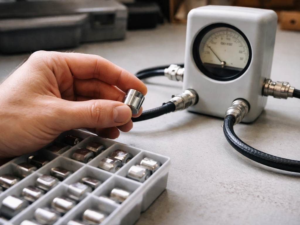
- Select the right slug. Check the slug's label for its frequency range and full-scale wattage. Your operating frequency must fall within the slug's rated range, and your expected power level should be below the slug's maximum. Using a slug that's too small for the power level will damage it.
- Orient the slug correctly. The slug body has an arrow or a label indicating the direction of forward power flow. Point the arrow toward your load (antenna or device), not toward the source. If you want to measure reflected power, flip the slug so the arrow points toward the source.
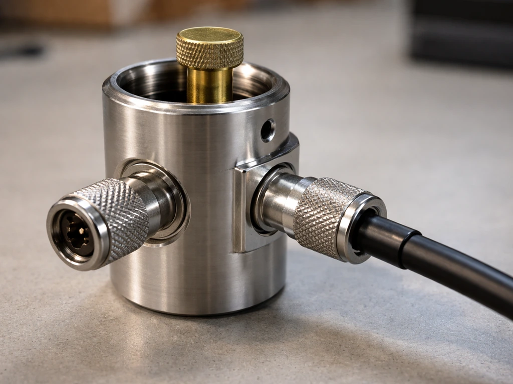
- Connect the meter in-line. With the RF source still off, connect one coax jumper from your RF source output to the INPUT port of the Bird meter, and a second jumper from the OUTPUT port of the meter to your load. The meter has two N-type connectors; on the 4304A these are clearly labeled.
- Insert the slug. Slide the slug into the meter's element socket and give it a quarter-turn to lock it in place. Bird's own safety warning is explicit here: the element socket can have RF voltage present during operation, so always have the slug seated before you power up. Never operate the meter with an empty socket.
- Power on the RF source. Bring it up gradually if possible. The meter needle (or digital display) should deflect immediately once RF is present.
- Read the forward power. Note the value on the scale that matches your slug's full-scale rating. If you want reflected power, power down, flip the slug 180 degrees, and power up again to take the second reading.
- For digital models like the 4421A: after powering up, the display defaults to Average Power mode. You can navigate the menu to switch display screens to show VSWR, Return Loss, or Reflected Power without physically flipping the slug, since the digital sensor handles directionality internally.
Common wiring scenarios
| Scenario | Source side connection | Load side connection | Slug orientation |
|---|---|---|---|
| Measuring transmitter output power | Transmitter RF output | Dummy load or antenna | Arrow toward load |
| Checking antenna match (reflected power) | Transmitter RF output | Antenna | Arrow toward source (flipped) |
| Verifying amplifier gain | Amplifier output | Dummy load | Arrow toward dummy load |
| Continuous in-line monitoring | Transmitter RF output | Antenna | Arrow toward antenna, leave in place |
How to read the results correctly
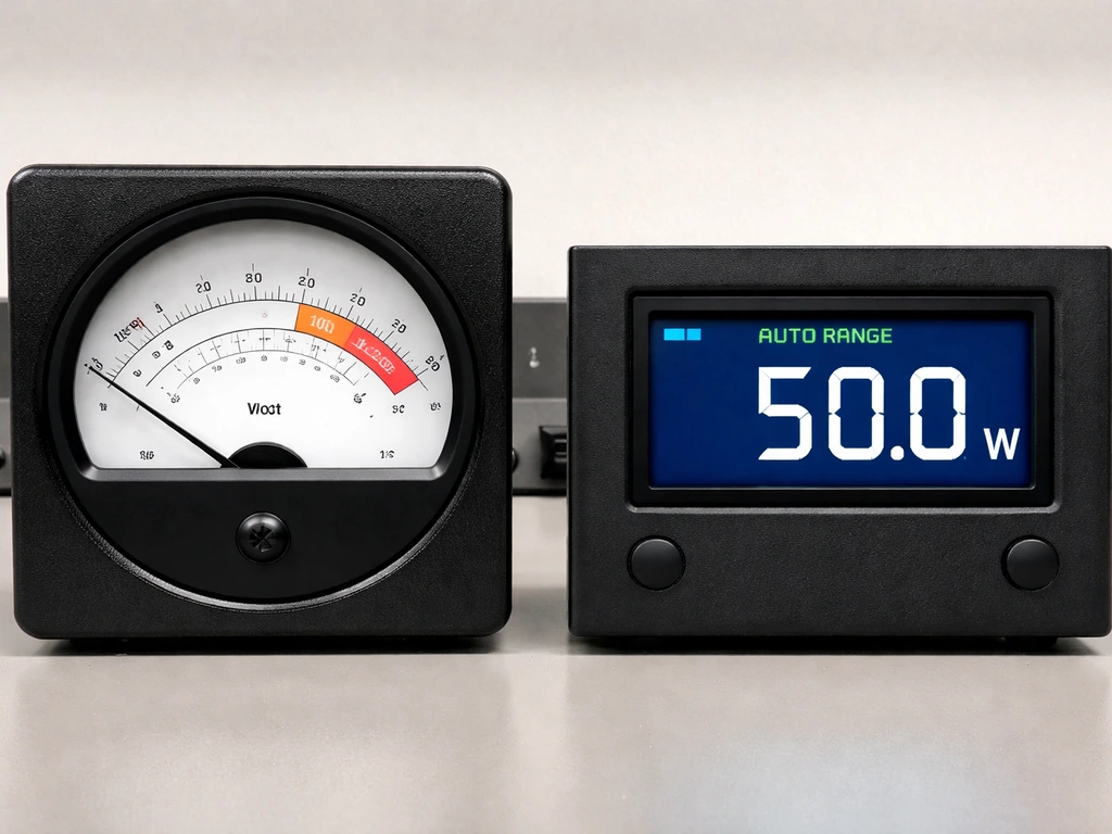
On an analog Bird meter like the 43 or 4304A, the meter face has multiple arcing scales printed on it. You read the scale that matches your slug's full-scale wattage rating. If your slug is rated for 100 watts full scale, read the 100W arc. Ignore the other scales entirely. The needle's position on that arc gives you your power in watts.
On the digital 4421A, the display defaults to Auto Range, which automatically picks the best scale for your current power level. You can switch to Manual Range if you prefer a fixed scale, but note that manual range is not available when the display unit is set to dBm. The screen can show Forward Power, Reflected Power, VSWR, and Return Loss on separate display pages, and you can cycle through them using the front-panel controls.
A healthy RF setup will typically show high forward power close to your transmitter's rated output and low reflected power (ideally less than 5% of forward power). A VSWR of 1.5:1 or lower is generally considered acceptable for most setups. If reflected power is climbing toward 10% or more of forward power, that's a sign of a real mismatch worth investigating before continuing to transmit. If you want to apply this kind of measurement to field work, use consistent sampling methods and counts to figure out how to count bird populations over time.
One thing beginners often miss: the Bird wattmeter measures real (active) power in watts, not apparent power in volt-amps. In a well-matched 50-ohm RF system, the power factor is effectively 1, so this distinction rarely matters. But if you're comparing Bird readings against other instruments that might report apparent power, keep in mind that apparent power (VA) can read higher than real power (watts) when there's a significant reactive component in the load.
Troubleshooting common problems
No reading at all
- Check that the RF source is actually transmitting. Use a separate indicator (LED on the transmitter, software power indicator) to confirm RF is being generated.
- Confirm the slug is fully seated and locked. A slug that's only halfway in won't make proper contact.
- Verify you're reading the correct scale for your slug. A 10W slug with a 500W signal will peg immediately and look broken; a 500W slug with a 1W signal will barely move.
- Check your coax connectors. A loose or poorly tightened N-connector can break the RF path entirely.
Flickering or unstable readings
- A fluttering needle almost always means a loose connection somewhere in the coax path. Tighten every connector and try again.
- If you're transmitting SSB or amplitude-modulated signals, the power naturally varies with the audio envelope. That's normal. Use a dummy load and a constant carrier (CW or FM) for a stable reference measurement.
- On the 4421A, if Auto Range is jumping between scales constantly, switch to Manual Range and pick a fixed scale that covers your power level.
Readings that seem obviously wrong
- If forward power reads much lower than expected, check that the slug arrow is pointing toward the load, not the source. An incorrectly oriented slug will read reflected power instead of forward power.
- If reflected power reads higher than forward power, something is seriously wrong with the load or the coax between the meter and the load. Check for a shorted or open-circuit antenna connection.
- If readings are consistently off by a fixed percentage, the slug may be damaged or out of calibration. Bird slugs can be sent back to Bird for recalibration. Remember, calibration lives in the slug, not the display unit.
- Double-check that your operating frequency is within the slug's rated frequency range. A slug used outside its rated band will give meaningless readings.
Safety checks before assuming the meter is faulty
- Visually inspect the slug for physical damage, burned areas, or a cracked housing. A damaged slug should be replaced, not used.
- Inspect the center pin and threads on both N-type connectors on the meter body for damage or corrosion.
- Test with a known-good source and dummy load to isolate whether the problem is the meter, the source, or the load.
Best practices and safety tips for confident use
The most important safety rule for any Bird thru-line wattmeter is this: never operate the meter with the slug socket empty. Bird's own manual for the 4304A explicitly warns that RF voltage may be present in the element socket during operation. An empty socket exposes that live point. Always insert the slug before applying RF power, and always remove RF power before pulling the slug out.
Never open the meter body or attempt to replace internal components while any RF power is applied. Bird's documentation for the 43-series is equally clear on this: do not make adjustments or replace components with the RF power on. Even at moderate power levels, RF energy in a transmission line can cause burns or equipment damage if mishandled.
- Always match your slug's power rating to your actual power level with a comfortable margin. If you're running 100 watts, use a 100W or 200W slug, not a 10W slug.
- Keep the meter's connectors and the slug contacts clean and dry. Moisture or oxidation on N-type connectors is a surprisingly common cause of erratic readings.
- Store slugs in their individual cases when not in use. The sensing elements inside are precision components and don't appreciate being rattled around loose in a toolbox.
- If you're measuring an unknown transmitter for the first time, start with a high-range slug and work downward. It's much better to get a low but safe reading first than to blow a slug by underestimating the power.
- Label your slugs clearly with a marker or label tape. When you have several with similar housings, mixing them up is an easy and frustrating mistake.
- Periodically verify your meter against a known calibrated source if accuracy matters for your work. Bird's recommendation is to send slugs in for periodic recalibration rather than calibrating the display unit.
Once you get comfortable with the Bird wattmeter, you'll find yourself reaching for it constantly as a sanity check whenever something in an RF setup seems off. It's one of those tools that pays for itself the first time it catches a bad coax run or a failing antenna before you spend hours chasing the problem elsewhere. If you're also exploring how to measure or evaluate bird-related equipment in other ways, topics like how to weigh a bird or how to conduct a bird survey involve similar careful observation and measurement principles that build the same disciplined habits.
FAQ
How do I know which direction to orient the Bird wattmeter so the forward and reflected readings make sense?
Verify the meter’s directional arrow or slug orientation against the RF flow (source toward load). A quick sanity check is to transmit at low power, then see whether reflected power rises when you intentionally introduce a deliberate mismatch (for example, a temporary attenuator or known dummy load that is not well matched). If the reflected reading responds opposite to what you expect, rotate the slug or re-seat it correctly and re-check.
What should I do if my forward power reading is stuck at zero or jumps around?
First confirm the correct slug is installed for both your frequency range and expected power range, and that the slug socket is fully seated. Then check connectors and center conductor contact (loose or damaged connectors can lead to open-circuit behavior). Finally, ensure the transmitter output is actually enabled and you are measuring the right path (between the correct RF source and the correct load).
Can I use a Bird wattmeter on coax systems that are not 50 ohms (for example 75 ohm cable)?
You can physically insert it into many coax runs, but accurate readings require a 50-ohm environment because the slug and meter are calibrated for that impedance. With a different line impedance, forward/reflected separation and derived VSWR will be unreliable, so use a 50-ohm line segment, a matching network, or a meter intended for that impedance.
How do I choose the right slug and power range so I do not damage the sensor or get misleading numbers?
Pick a slug whose frequency rating covers your operating frequency and whose power handling is comfortably above your maximum expected forward power. If your readings frequently peg at the top scale, you are outside the intended measurement range (or close enough to reduce accuracy). If you are unsure, start with a lower-power setting from the transmitter and confirm the display stabilizes on the expected scale.
What is the safest procedure for swapping slugs during troubleshooting?
Turn RF output off before removing or inserting the slug. Let the system settle, then insert the correct slug fully, orient it correctly, and only then re-enable RF. Treat the slug socket as energized risk when RF has been applied recently, and never work inside the meter body while RF power is possible.
Why does the Bird wattmeter report forward and reflected power, but VSWR still seems too high or too low?
VSWR depends on both forward and reflected power readings. If reflected power is near the meter’s noise floor, small measurement errors can make VSWR appear exaggerated or unstable. Use enough forward power to get a stable reflected reading, and confirm you selected a slug with the correct frequency range because out-of-range sensing can distort directionality.
How should I interpret reflected power percentages like “less than 5% is good”?
That guideline assumes a typical 50-ohm RF setup and that the measurement is truly between the transmitter and the antenna/load you care about. Always compare reflected to forward power under the same operating mode (CW versus pulsed can change averages). For pulsed operation, check whether the meter is set to Average Power or Pulse Power so the percentage comparison matches how the load is behaving.
What is the difference between real power (watts) and apparent power (VA), and when will it actually matter for my setup?
Bird measures real (active) power in watts. If your load is not purely resistive (for example, significant reactive mismatch), apparent power ratings or other instruments that report VA may show higher numbers than the Bird wattmeter. It matters most when you are comparing against power meters that calculate or report different definitions, or when you are tuning antennas and want to avoid confusing VA with delivered real RF energy.
On the 4421A, why can’t I use Manual Range when the display is set to dBm?
The instrument ties dBm scaling to a logarithmic reference and handles range selection differently. If you need stable watt-to-watt comparisons across different power levels, switch out of dBm mode so you can use a fixed manual range, then record readings consistently.
My VSWR looks acceptable, but the transmitter still alarms or sounds like it is limiting output. What could be wrong?
First confirm the measurement point matches the protection point. A wattmeter reading taken at the antenna feed may show good match while the transmitter protection is reacting to reflected energy at a different location. Also check that your measurement includes the directional path correctly (arrow orientation and slug direction). Finally, consider that some systems alarm based on detector type, peak power, or timing, so compare against the meter’s Average versus Peak or Pulse Power settings.
Why does the Bird meter warn against running it with the slug socket empty?
An empty slug socket can expose live RF voltage at the sensing point during operation. With no element installed, that energized interface can be hazardous and can also compromise the accuracy or integrity of the measurement path. Always insert the slug before applying RF power, and remove it only after RF power is off.
Next Article
How to Count Bird Populations: Methods, Steps, and Estimates
Step-by-step guide to count bird populations using point counts, transects, and roost or feeder counts with detection-aw